


Introduction
Engineers specifying tolerances for 5-axis CNC machined parts face a universal dilemma: overly tight tolerances lead to skyrocketing costs and extended lead times, while overly loose ones result in assembly failures and performance issues. Industry observations suggest that up to 30% of manufacturing waste stems from specifying non-functional, excessively tight tolerances. The core problem is the traditional “one-size-fits-all” or guesswork-based approach to tolerance assignment, which lacks a systematic framework to link design intent, material behavior, manufacturing process capability, and cost. This disconnect forces teams into a cycle of expensive revisions and delayed projects.
This article introduces a data-driven, four-step framework to solve this. It guides you on how to scientifically define a hierarchy of tolerances based on functional necessity, understand the interplay between material properties and machining processes, and learn to critically evaluate a supplier’s true capability. The goal is to achieve the optimal balance of cost, schedule, and performance right from the first production run. So, how is this framework built and applied? Let’s deconstruct it step-by-step.
Why Does a “One-Size-Fits-All” Tolerance Approach Inevitably Lead to Waste?
This section analyzes the significant cost and time penalties of applying uniform, tight tolerances, arguing that waste is inevitable when tolerances are not aligned with the specific function of each part feature.
- The Steep Curve of Tolerance Cost: The relationship between tolerance and cost is not linear; it’s exponential. Tolerances follow a steep cost curve. Tightening a tolerance from ±0.1mm to ±0.05mm may increase cost by 20-30%. Tightening it further to ±0.025mm can easily double the cost. This is due to the compounding effects: longer machining times for lighter finishing cuts, the need for specialized tooling and high-end machines, increased scrap rates from processes pushed to their limits, and the necessity for 100% inspection rather than statistical sampling. Applying a blanket tight tolerance to all features indiscriminately triggers these cost multipliers across the entire part.
- The Critical Concept of the “Functional Feature”: The antidote to this waste is distinguishing between functional and non-functional features. A functional feature is one that interacts with another part — a bearing seat, a sealing surface, a critical mounting hole. These interfaces dictate performance and require precise control. Non-functional features, such as cosmetic surfaces, clearance pockets, or non-mating threads, do not. Specifying a tight tolerance on a non-functional feature is paying for precision that delivers zero functional benefit, the very definition of waste in an engineering tolerance guide. This principle is foundational in standards like ASME Y14.5, which provides the language to define and control these critical geometric relationships.
- The Ripple Effect on Lead Time and Complexity: Beyond direct cost, overly tight tolerances sabotage the schedule. They demand slower cutting speeds, more frequent tool changes, and often require secondary processes like precision grinding or lapping. Each added step introduces more handling, setup time, and potential for error. What could be a simple, efficient 5-axis program becomes a complex, multi-step ordeal. Understanding this is the first step in learning how to specify CNC tolerances intelligently and practicing true design for manufacturing tolerances.
What is the Step-by-Step Framework for Building a Functional Tolerance Hierarchy?
This section details the practical, four-step framework for assigning tolerances, moving from a holistic view of the part’s function to specific, justified numbers for each feature category.
1. Step 1: Identify Critical Functional Interfaces (The “What”)
Begin by analyzing the part’s role in the final assembly. Ask: “Which surfaces or holes mate with other components to transfer load, provide motion, or create a seal?” These are your Critical Functional Features. For a drone motor mount, this would be the bore for the bearing and the bolt circle for attachment. Highlight these features on the drawing. This step forces a discipline of function-first thinking, ensuring the most engineering effort is spent where it matters most.
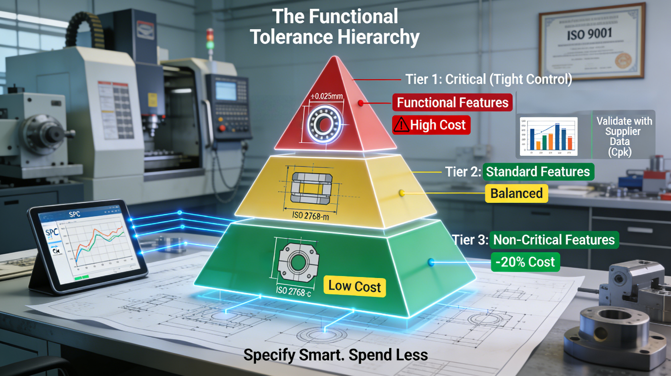
2. Step 2: Assign Tiers Based on Function (The “How Tight”)
Once identified, assign tolerances in tiers. Tier 1 (Critical): Apply the tightest tolerances, often referencing standards tighter than ISO 2768-m or using Geometric Dimensioning and Tolerancing (GD&T) like true position or profile of a surface. Tier 2 (Manufacturing Aids): These are features like fixture locators or datum surfaces used during machining. They can use standard machining tolerances (e.g., ISO 2768-m). Tier 3 (Non-Critical/General): All other features. Apply the loosest, most economical tolerances, such as ISO 2768-c. This creates a clear, justifiable hierarchy on the drawing.
3. Step 3: Apply and Document the Rationale
Document this hierarchy directly on the drawing or in a supporting document. Using a note like “tolerances per ISO 2768-m unless otherwise specified” establishes a sensible baseline, and any tighter callout immediately signals a critical feature to the machinist. This framework transforms tolerance specification from a guessing game into a transparent, data-driven engineering process, providing crucial precision machining insights. Executing this step effectively requires a deep understanding of both design intent and manufacturing reality, knowledge that is often encapsulated in specialized resources on 5-axis CNC machining tolerances.
How Do Material Properties Like Aluminum vs. Stainless Steel Dictate Tolerance Strategy?
This section explains that a specified tolerance is not just a number on a drawing; it is a challenge that interacts profoundly with the chosen material’s physical properties, requiring different strategies for different metals.
1. The Challenge of Ductile and Thermally Reactive Materials
Consider 6061 aluminum. It is relatively soft and has a high coefficient of thermal expansion. During machining, cutting forces and the heat generated can cause thin-walled sections to deflect elastically (“spring”) or distort thermally. Specifying a tight ±0.025mm profile on a large, thin aluminum plate may be impossible with standard machining; it may require stress-relieving the blank, using specialized climb milling strategies to minimize tool pressure, and machining in a temperature-controlled environment. The “achievable tolerance” is a product of the material’s behavior under the machining process.
2. The Challenge of Hard, Abrasive, and Work-Hardening Materials
Now consider 304 stainless steel. It is tougher, generates more heat, and has a strong tendency to work-harden. Aggressive or incorrect tool paths can create a hardened surface layer that subsequent passes cannot cut, leading to tool deflection and poor accuracy. Achieving the same ±0.025mm tolerance requires sharp, coated carbide tools, lower cutting speeds to manage heat, and possibly trochoidal milling to maintain constant chip load and prevent work hardening. The process to hit the number is fundamentally different.
3. The Supplier’s Role as a Material-Process Expert
Therefore, a competent manufacturer doesn’t just read a tolerance; they interpret it through the lens of the specified material. They maintain a material-specific process library that details feeds, speeds, tooling, and strategies proven to achieve target tolerances consistently. This is where a supplier’s depth of experience, often formalized in quality systems like IATF 16949, becomes invaluable. Their process controls must account for these material variances to ensure stability, making them a true partner in advanced machining processes for tight tolerance 5-axis machining.
What Evidence Should You Demand in a Supplier’s “Tolerance Capability Report”?
This section provides a checklist of verifiable data points that move beyond a supplier’s marketing claims to objectively assess their true ability to hold specified tolerances consistently in production.
1. Statistical Process Control (SPC) Data: Proof of Consistency
Anyone can make one good part. The key question is: “Can you make the ten-thousandth part identical to the first?” Demand to see Statistical Process Control (SPC) charts for critical dimensions on a past, similar project. Look for a Process Capability Index (Cpk or Ppk) greater than 1.33. This statistical measure proves their process is not only centered within the tolerance band but has minimal variation, indicating a stable, predictable, and capable manufacturing process. This is the single most important piece of evidence for precision machining services.
2. Measurement System Analysis (MSA): Trust in the Data
The SPC data is only as good as the measurements behind it. Request a Measurement System Analysis (MSA) or Gage R&R report for the inspection equipment used. A Gage R&R result below 10% is excellent, indicating the measurement variation is a tiny fraction of the tolerance band, meaning the data is highly reliable. This validates that the supplier’s quality checks are trustworthy, a requirement embedded in standards like ISO 9001 for process control and measurement device verification.
3. Environmental and Machine Condition Documentation
Precision machining is sensitive to its environment. Inquire about their shop floor temperature and humidity control. For micron-level work, fluctuations greater than ±1-2°C can cause measurable thermal growth in both the machine and the part. Also, ask for records of machine calibration and preventive maintenance. A well-maintained, climate-controlled environment is not a luxury for high-precision work; it is a prerequisite. This comprehensive audit approach separates shops that truly understand 5-axis CNC machining tolerances from those that merely own the equipment.
Can You Share a Real-World Case of Tolerance Optimization Balancing Cost and Performance?
This section presents a hypothetical but realistic case study based on common industry challenges, illustrating how the application of the tolerance hierarchy framework directly leads to significant cost savings without compromising part function.
1. The Initial Challenge: Over-Specification Threatening Project Viability
A client designed a complex structural bracket for an unmanned aerial vehicle (UAV). The initial drawing applied a blanket tolerance of ±0.05mm to virtually every dimension, driven by a general desire for “high quality.” The quotes from several machine shops came in 40% over budget, jeopardizing the project. The client believed the tight tolerances were necessary for the lightweight, stiff design.
2. The Collaborative Analysis: Applying the Functional Hierarchy
In review, the engineering team performed a functional tolerance analysis. They identified that only three feature groups were truly critical: the interface for the flight controller (requiring precise location), the mounting surface for the motor (requiring flatness and perpendicularity), and the bearing bores (requiring size and roundness). The numerous cooling fins, lightening pockets, and cosmetic radii served no load-bearing or alignment function.
3. The Outcome: Targeted Precision, Major Savings
The drawing was revised. The critical features retained their ±0.05mm (or equivalent GD&T) controls. The non-critical features were relaxed to a general tolerance of ±0.2mm. Re-quoted with the updated drawing, the manufacturing cost dropped by 22%, bringing the project back within budget. The part performed flawlessly in testing, as the precision machining services were focused only where it mattered. Through this value engineering analysis, the project was successfully de-risked and launched.
What Are the Critical Questions to Ask Before Finalizing Your Tolerance Specs?
This final section provides a practical checklist of questions for designers and engineers to use as a final review before releasing a drawing, ensuring the tolerance strategy is robust, functional, and manufacturable.
- The Function and Assembly Test: For every dimension with a tight tolerance, ask: “What is the explicit functional or assembly reason for this specific tolerance?” If you cannot articulate a clear answer (e.g., “for clearance with part X,” “to ensure seal compression”), the tolerance is likely arbitrary and should be relaxed to a standard machining value. This is the core of a CNC machining tolerance guide.
- The Manufacturing Reality and Data Test: Challenge your assumptions with data: “Have we seen historical process capability data (Cpk) from a qualified supplier proving this tolerance can be held consistently in production on this material?” and “If this is a new design, have we involved a manufacturing engineer in a Design for Manufacturability review to assess feasibility?” Engaging manufacturing expertise early prevents costly, late-stage discoveries that the design is unproducible as drawn.
- The Cost-Benefit and Risk Test: Finally, perform a risk assessment: “What is the consequence of this feature being at the very limit of its tolerance band? Would it cause a functional failure, or is it merely a theoretical deviation?” and “If we relaxed this tolerance by one grade (e.g., from ±0.05mm to ±0.1mm), what is the estimated cost saving, and does it outweigh any potential performance risk?” Asking these questions formalizes the decision-making process, ensuring every tight tolerance on the drawing is a conscious, justified investment. This disciplined approach is the essence of knowing how to specify CNC tolerances effectively.
Conclusion
Specifying 5-axis CNC tolerances effectively is a balancing act that requires shifting from “numbers on a drawing” to “function-based system decisions.” By applying a hierarchical framework that prioritizes critical features, understanding the profound interaction between materials and processes, and rigorously validating supplier capability with hard data, engineering teams can dramatically reduce manufacturing costs, mitigate project risk, and ensure first-time success. This transforms tolerance specification from a source of overruns and delays into a lever for predictable, high-quality outcomes.
FAQs
Q: What is a realistic tolerance range I can expect for standard 5-axis machining of aluminum parts?
A: For most aluminum components, holding tolerances of ±0.05mm to ±0.1mm is considered commercially viable on quality 5-axis machines. Tighter tolerances like ±0.025mm are possible but increase cost significantly due to slower processes and specialized tooling. Tolerances beyond ±0.01mm fall into ultra-precision territory, requiring exceptional environmental and machine control.
Q: How does geometric tolerancing (GD&T) differ from standard +/- tolerances in 5-axis machining?
A: +/- tolerances create a square tolerance zone, which can be restrictive and wasteful. GD&T, like position or profile tolerances, defines a uniform boundary (cylindrical or 3D), often allowing more manufacturing freedom while better controlling the functional relationship between features. For complex 5-axis parts with contours and angled features, using profile of a surface GD&T is typically more appropriate and manufacturable than multiple +/- linear dimensions.
Q: Should I specify different tolerances for prototyping vs. production runs?
A: The tolerance should be based on part function, not volume. However, the validation focus differs. Prototyping uses First Article Inspection (FAI) to verify the design. Production requires Statistical Process Control (SPC) to prove the process can hold the tolerance consistently. A good supplier should manage both, but the cost per part for a tight tolerance is usually higher in low volume due to intensive setup and validation.
Q: How do post-processing steps like anodizing affect final part tolerances?
A: Coatings like anodizing add material thickness — typically 0.005mm to 0.03mm per surface. This must be accounted for in the “as-machined” tolerances, especially for press-fit holes or threads. A competent manufacturer will recommend pre-plate dimensions to ensure the final, coated part meets specification. Early communication about required finishes is crucial.
Q: What is the most common mistake you see in tolerance specification on drawings?
A: The most costly mistake is applying a blanket tight tolerance to all dimensions. This ignores functional hierarchy and inflates cost without benefit. Another is omitting geometric tolerances for relationships between features (like perpendicularity or true position), leading to assembly issues even if all individual +/- dimensions are met. Always specify based on function and consult manufacturing experts during design.
Author Bio
This article is based on the insights of senior manufacturing engineers with deep expertise in precision component production. The team at LS Manufacturing is a certified precision manufacturing partner (ISO 9001, IATF 16949, AS9100D) focused on providing complex 5-axis CNC machining services for aerospace, medical, and automotive sectors. Need a cost-effective tolerance strategy for your next complex component? Contact their engineering team today for a free manufacturability review.